Unlike a gate valve (which is designed for fully open or fully closed service), a globe valve excels at throttling—providing fine, precise control over flow rate. This makes it a go-to choice for steam lines, cooling systems, fuel oil systems, and any process requiring accurate flow adjustment.
Globe Valve Cross-Section Diagram — Explained
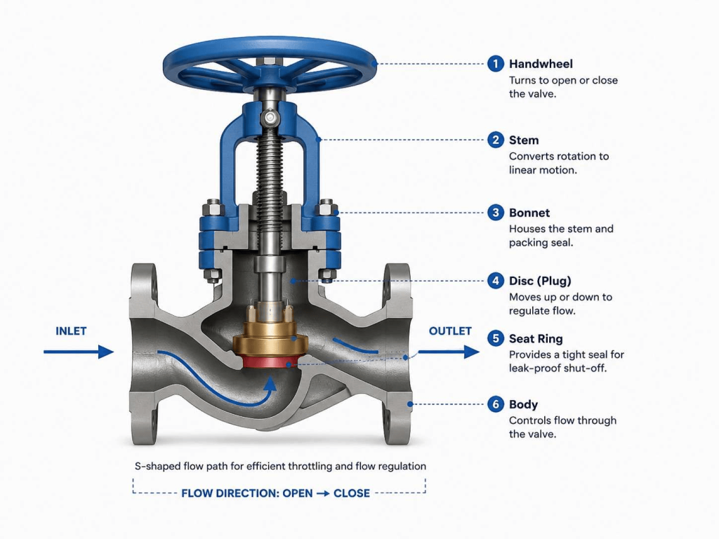
The diagram below shows a globe valve in the open position, with the disc raised above the seat and fluid flowing through the S-shaped internal path.
Detailed cross-section showing all major components: handwheel at top, stem, bonnet with packing, disc raised above seat ring, globe-shaped body, and horizontal inlet/outlet pipes with S-shaped flow path arrows.
Key Parts of a Globe Valve
Every globe valve has six core components working together. Understanding each part is essential to understanding why globe valves behave the way they do.
| # | Part Name | Material (Typical) | Function |
|---|---|---|---|
| ① | Handwheel | Cast iron, steel | Manually turns the stem to open or close the valve. Larger wheels provide more torque for high-pressure lines. |
| ② | Stem | Stainless steel, Monel | Converts the rotational motion of the handwheel into linear (up-down) motion of the disc. May be rising or non-rising. |
| ③ | Bonnet | Cast steel, forged steel | Houses the stem, packing, and gland. Connects the valve body to the actuating mechanism above. Packing prevents leakage along the stem. |
| ④ | Disc (Plug) | Stainless steel, brass, PTFE-faced | The primary closure element. Moves toward or away from the seat to reduce or increase the flow opening. Shape can be flat, plug, or needle type. |
| ⑤ | Seat Ring | Hard-faced alloy, stainless steel | The fixed mating surface against which the disc presses. When disc and seat meet fully, the valve is closed and flow stops. |
| ⑥ | Globe Body | Cast steel, forged steel, CI | The spherical shell that contains the internal baffle and chamber. Its shape creates the characteristic S-shaped flow path. |
Working Principle — Step by Step
The globe valve operates on a simple linear motion principle. Here is exactly what happens when you open or close one:
Turn the handwheel
Rotating the handwheel clockwise turns the threaded stem. The stem’s threads engage with the bonnet threads, translating rotation into downward linear movement. Anti-clockwise rotation raises the stem.
Disc moves linearly
The stem is rigidly connected to the disc. As the stem moves down, the disc moves down toward the seat ring. As it moves up, the disc lifts away from the seat, opening the valve port progressively.
Flow is throttled through the annular gap
With the disc partially raised, an annular (ring-shaped) gap exists between the disc face and the seat ring. The size of this gap directly controls the volumetric flow rate — smaller gap means less flow.
Fluid follows the S-shaped path
Inside the globe body, the internal baffle forces fluid to travel downward through the disc-seat gap, turn 90°, flow across the bottom chamber, turn 90° again, and exit upward on the other side — creating the characteristic S-shaped flow path.
Fully closed — tight shutoff
When the handwheel is turned fully clockwise, the disc presses firmly against the seat ring, compressing the seating surfaces together. This creates a metal-to-metal (or soft-seated) seal that stops flow completely.
The S-Shaped Flow Path — Why It Matters
The defining feature of a globe valve is the S-shaped (or Z-shaped) internal flow path. Unlike a gate valve or ball valve where fluid travels in a straight line, the globe valve forces fluid to change direction twice:
- Fluid enters horizontally through the inlet.
- It turns downward through the disc-seat opening (the control point).
- It crosses the lower chamber horizontally.
- It turns upward and exits through the outlet.
The pressure drop across a globe valve is typically 3–5× higher than a comparable gate valve at the same flow rate. This is intentional — the resistance is what allows fine flow regulation.
Types of Globe Valves
Globe valves are available in three body configurations, each suited to different piping layouts and flow characteristics:
1. Z-Body (Standard) Globe Valve
The most common type. The seat is horizontal and perpendicular to the pipeline. Fluid makes the classic Z-shape (two 90° turns). Best for general flow control and throttling. Available as forged steel or cast steel globe valves.
2. Y-Body Globe Valve
The seat and stem are inclined at approximately 45° to the pipe axis. This reduces the number of direction changes, lowering the pressure drop compared to a Z-body. Preferred for high-pressure, high-temperature steam service where pressure recovery is important.
3. Angle Globe Valve
The inlet and outlet ports are at 90° to each other (the valve acts as both a valve and an elbow fitting). Fluid makes only one turn, further reducing pressure drop. Useful in systems with limited space or where an elbow fitting would otherwise be needed.
Industrial Applications of Globe Valves
Globe valves are preferred wherever precise flow control matters more than minimising pressure drop. Key industries and applications include:
Oil & Gas
Wellhead flow control, fuel gas lines, compressor bypass lines, and instrument air systems.
Power Generation
Steam admission valves, turbine bypass, boiler feedwater systems, and cooling water regulation.
Chemical & Petrochemical
Reactor feed control, chemical dosing, pressure let-down stations, and coolant circuits.
Pharmaceutical
Sterile process flow regulation, clean steam systems, and purified water distribution.
Sugar & Distilleries
Juice flow control, steam injection, condensate return lines, and syrup regulation.
Water Treatment
Chemical dosing, filter backwash control, and flow balancing in distribution systems.
Globe Valve vs Gate Valve vs Ball Valve
Choosing the right valve type depends on whether your priority is flow control, pressure drop, or shutoff speed. Here is a direct comparison:
| Feature | Globe Valve | Gate Valve | Ball Valve |
|---|---|---|---|
| Primary use | Flow throttling & regulation | On/off isolation | Quick on/off shutoff |
| Flow control | ✔ Excellent | ✘ Poor | ✘ Limited |
| Pressure drop | High (S-path) | Low (straight bore) | Very low (full bore) |
| Shutoff tightness | ✔ Good | ✔ Good | ✔ Excellent |
| Operation speed | Slow (multiple turns) | Slow (multiple turns) | Fast (quarter turn) |
| Throttling life | ✔ Long — disc designed for it | ✘ Short — disc erodes | ✘ Poor — seals wear |
| Maintenance | Moderate — re-seat possible | Moderate | Low — simple design |
| Cost | Moderate | Low–moderate | Low–high (varies) |
Frequently Asked Questions
Why is it called a globe valve?
The name comes from the spherical or globe-shaped external body of the valve. Historically, early designs had a very pronounced spherical shape. Even modern designs retain the rounded body profile, distinguishing them from flat-bodied gate valves or cylindrical ball valves.
Can a globe valve be used for on/off service?
Yes, but it is not ideal. Globe valves can fully open and fully close, but they require multiple turns and cause a high pressure drop even when fully open. For pure on/off isolation, a gate valve or ball valve is more appropriate and economical.
In which direction should a globe valve be installed?
For most applications, flow should enter under the disc (from the high-pressure side into the lower chamber). This orientation reduces seat erosion and makes the valve easier to open against pressure. The flow direction arrow is typically cast onto the valve body.
What is the difference between a forged steel and cast steel globe valve?
Forged steel globe valves are produced by mechanically deforming steel under high pressure, resulting in a denser, stronger, and more homogeneous grain structure. They are preferred for high-pressure, high-temperature, and critical service applications. Cast steel globe valves are made by pouring molten steel into moulds and are suited for larger sizes and moderate pressure-temperature conditions at lower cost.
How do I know when a globe valve needs maintenance?
Common indicators include visible leakage from the packing gland (around the stem), inability to fully stop flow when closed (disc or seat wear), increased operating torque on the handwheel, or external body corrosion. Regular inspection per a documented maintenance schedule is recommended for critical service valves.
What standards do Flowjet globe valves comply with?
Flowjet Valve manufactures globe valves in accordance with international standards including API 602, BS 1873, ASME B16.10, ASME B16.25, and relevant material standards such as ASTM A105, ASTM A216 WCB, and ASTM A351 CF8M. Full certification documentation is available on request.
Need Globe Valves for Your Project?
Flowjet Valve manufactures forged steel and cast steel globe valves for oil & gas, power, chemical, and pharmaceutical industries — from our facility in Ahmedabad, India.