
A new maintenance engineer once asked me something that most experienced people never bother to explain properly.
He pointed at a ball valve on a cooling water line and said, “I know it opens and closes. But what actually happens inside when I turn that handle?”
It’s a fair question. Ball valves are everywhere in industrial plants — oil and gas, chemical, pharmaceutical, water treatment, power. Engineers specify them daily. Operators turn them every shift. But the actual working principle — what happens inside the body, how the seal forms, why one design works better than another at high pressure — isn’t something most people stop to think through.
This guide explains it properly. How an industrial ball valve works, what’s inside it, how the two main designs differ, how actuation works, and what causes failures. If you’re an engineer, a buyer, or someone who works with valves regularly, this is the explanation worth having.
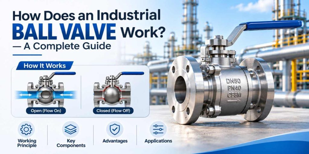
The Core Idea — Quarter-Turn, Full Bore
Before getting into the parts, here’s the principle in one sentence: a ball valve controls flow by rotating a ball with a hole through its centre, so the hole either lines up with the pipe (open) or sits perpendicular to it (closed).
That’s it. Everything else — the seat design, the pressure rating, the actuation method — is about how that rotation is made reliable, leak-proof, and appropriate for the specific service condition.
The quarter-turn refers to the 90-degree rotation from fully open to fully closed. Turn the handle 90 degrees one way — open. Turn it 90 degrees the other — closed. This simplicity is part of why ball valves dominate process industries. Fast operation. Clear visual indication of valve position. No multi-turn handwheel, no rising stem, no guesswork about whether the valve is open or shut.
What’s Inside a Ball Valve — The Main Components
Open a ball valve and you find five key parts. Understanding what each one does explains both how the valve works and why a well-made valve lasts longer than a poorly-made one.
1. The Body
The body is the outer shell — the pressure-containing structure that holds everything together. It connects to the pipeline through flanged, butt-weld, socket-weld, or screwed end connections depending on the application. Body material is chosen based on the fluid service: carbon steel WCB for oil and gas, stainless steel CF8M for chemical and corrosive service, low-temperature LCB for sub-zero applications.
The body must withstand the full operating pressure of the system — not just static pressure, but dynamic pressure surges and waterhammer events that occur in real process plants. This is why body testing matters. At Flowjet Valve’s Ahmedabad facility, every ball valve body undergoes hydrostatic shell testing at 1.5 times the rated working pressure before assembly — not on a sample basis, but on every single unit.
2. The Ball
The ball is the working element — a spherical component with a cylindrical bore (the port) through its centre. When the port aligns with the pipeline, flow passes through. When the ball rotates 90 degrees, the solid portion of the ball faces the flow and blocks it completely.
Ball material and surface finish matter significantly. The sealing surface of the ball must be hard enough to resist wear from the seat material rubbing against it during operation, smooth enough to maintain a reliable seal, and corrosion-resistant for the specific fluid it handles. Chrome-plated carbon steel balls are standard for general oil and gas service. Solid stainless steel balls are used for chemical and food service. Stellite-coated or hard-chrome balls are used in high-temperature and abrasive service.
Port size is either full bore (the port diameter matches the pipe bore) or reduced bore (the port is smaller). Full bore valves allow pigging, reduce pressure drop, and are standard for most pipeline and process applications. Reduced bore valves are more compact and lighter — sometimes acceptable in utility service where pressure drop and pigging aren’t concerns.
3. The Seats
The seats are the sealing elements that press against the ball to prevent leakage in the closed position. They sit on both upstream and downstream sides of the ball. This is the component most critical to the valve’s sealing performance, and it’s the component that wears out first in demanding service.
PTFE (polytetrafluoroethylene) is the most common seat material in industrial ball valves. It’s chemically inert to most process fluids, it conforms slightly to the ball surface to give a reliable seal, and it handles temperatures up to around 180°C. For higher temperatures or abrasive service, RTFE (reinforced PTFE with glass or carbon fill) gives better mechanical strength. For fire-safe designs and very high-temperature service, metal-to-metal seats with Stellite hard-facing replace elastomeric and polymer seats entirely.
The seat design — specifically how the seat presses against the ball — is where the difference between floating and trunnion designs becomes most important. More on that in a moment.
4. The Stem
The stem connects the ball to the external operator — the lever handle, the gear operator, or the actuator. When the operator turns the stem, the ball rotates with it.
Stem design affects two critical things: torque transmission and fugitive emissions. The stem must transmit operating torque without deflecting or failing under the loads generated at high pressures and large diameters. And the stem seal — typically graphite packing or a polymer seal set — must prevent the process fluid from escaping along the stem bore to atmosphere.
Anti-blowout stem design is a standard requirement in modern industrial ball valves. Without it, a stem under full line pressure can be ejected if the external packing is removed or fails — a serious safety hazard. Reputable manufacturers like Flowjet Valve incorporate anti-blowout stems as a standard feature, not an option.
5. The Gland / Packing Assembly
The gland holds the stem packing in place and allows the packing load to be adjusted. Properly loaded packing prevents leakage along the stem while still allowing the stem to rotate. Over-tightened packing increases operating torque and accelerates stem wear. Under-tightened packing allows fugitive emissions.
Floating Ball Valve — How It Works
A floating ball valve is the simpler of the two main designs. The ball is not fixed — it “floats” between the two seats, held in place only by seat contact. Under line pressure, the upstream pressure pushes the ball against the downstream seat, increasing the contact force and improving the seal.
This self-energising seal mechanism is what makes floating ball valves reliable and cost-effective for low to medium pressure service. As pressure increases, the seating force increases. The valve seals better under pressure than it does at zero pressure — a useful characteristic.
The limitation comes at high pressures and large diameters. As pressure increases, the force pushing the ball against the downstream seat becomes very high. This force must be reacted entirely through the downstream seat. At high pressures or in large sizes, this creates unacceptably high seat loads, seat deformation, and very high operating torque. The stem and operator must generate enough torque to rotate the ball against this contact force — which becomes impractical in large, high-pressure applications.
Floating ball valves are the right choice for: general process service, utility service (water, air, steam), pipeline service in Class 150 and Class 300 at moderate diameters, chemical injection, instrumentation isolation, and most applications where the pressure-diameter combination keeps seat loads manageable.
Flowjet Valve manufactures floating ball valves from DN15 to DN200 (½” to 8″) in ASME Class 150 to Class 600, with carbon steel, stainless steel, and low-temperature body materials.
Trunnion Mounted Ball Valve — How It Works
A trunnion mounted ball valve solves the high-pressure, large-diameter limitation of the floating design. The ball is mechanically fixed — supported at top and bottom by trunnion bearings that absorb the line pressure thrust loads.
Because the ball doesn’t move axially, the seats can’t rely on line pressure to generate seating force. Instead, trunnion valves use spring-loaded seats — the springs hold the seats against the ball even at zero pressure, maintaining a seal. When line pressure is applied, the upstream pressure actually helps push the upstream seat away from the ball slightly (this is the pressure-energised seat concept), while the downstream seat maintains contact through spring force.
This design has two important consequences. First, operating torque is much lower relative to pressure class and size, because the stem only needs to rotate the ball — it doesn’t have to overcome the full seat contact force that line pressure generates in a floating valve. Second, the valve can be designed for double-block-and-bleed service — both upstream and downstream seats seal independently, with a cavity vent between them.
Trunnion ball valves are standard for: large diameter pipeline service (DN200 and above), high-pressure Class 600 and above applications, mainline pipeline block valves, compressor station isolation, wellhead service, and any application requiring double-block-and-bleed capability.
Flowjet Valve’s trunnion mounted ball valves are manufactured to API 6D for pipeline service and tested to API 598. They’re available in sizes from DN50 to DN600 (2″ to 24″) in ASME Class 150 to Class 2500.
Fully Welded Ball Valve — The Buried Pipeline Design
Fully welded ball valves work on the same principle as standard flanged designs — floating or trunnion ball mechanism, PTFE or metal seats — but with one critical difference: the body is welded into a single sealed unit with no external bolted joints.
Why does that matter? In a bolted body valve, there are potential leak paths at every body joint. For buried pipeline service — underground gas distribution, district heating, long-distance pipeline — an external leak is not a maintenance problem you can monitor and schedule. It’s an excavation. The elimination of body joints removes that risk entirely.
Fully welded ball valves are built to last without maintenance access. They’re heavier and more expensive than bolted designs, and they can’t be disassembled in the field. For the applications they’re designed for, those are acceptable trade-offs.
3-Piece Ball Valve — The Maintenance-Friendly Design
A 3-piece ball valve has a separable centre body section. The two end pieces stay bolted in the pipeline. The centre section — containing the ball and seats — can be unbolted and removed without disturbing the pipe connections.
This makes seat replacement and ball inspection practical without a full valve removal. 3-piece designs are common in pharmaceutical and food processing (where frequent cleaning is routine), chemical injection systems, and any service requiring regular seat inspection.
How Ball Valve Actuation Works
A ball valve can be operated manually or through an actuator.
Manual operation: A lever handle gives direct quarter-turn operation. Fast, simple, clear visual position indication. Suitable for valve sizes up to DN50 or DN80 in most pressure classes before operating torque becomes too high for comfortable manual operation.
Gear operation: A worm gear operator multiplies mechanical advantage, allowing larger valves to be operated manually with reasonable effort. Standard for large diameter manual ball valves — DN100 and above in most pressure classes.
Pneumatic actuation: A pneumatic actuator uses compressed air to generate the torque needed to rotate the ball. Single-acting (spring-return) actuators fail to a defined position on air loss — open or closed depending on spring direction. Double-acting actuators use air for both opening and closing strokes, with no spring return. Pneumatic actuation is used when remote or automated operation is required, and when the control system uses pneumatic signals.
Electric actuation: An electric actuator uses a motor to drive the valve. Used when pneumatic supply isn’t available, when precise position control is needed, or when the valve is integrated into a DCS or BMS with 4–20mA or digital control signals.
Flowjet Valve supplies pre-assembled, pre-tested actuated ball valve packages — not just bare valve bodies. The actuator sizing is matched to the valve’s operating torque at the rated pressure class, so the assembly works correctly from day one rather than requiring site modification.
Why Do Industrial Ball Valves Fail?
Understanding how ball valves work makes the failure modes obvious.
Seat wear: The seat contacts the ball on every open and close cycle. PTFE seats wear over thousands of cycles. High-velocity flow, abrasive particles, and thermal cycling accelerate this. Result: seat leakage in the closed position. Fix: replace seats using a manufacturer that stocks the seat material you specified.
Stem packing leak: The stem packing degrades over time, especially in high-temperature or chemically aggressive service. Result: leakage visible at the stem gland. Fix: re-pack or replace stem packing. Proper material selection when specifying the valve avoids premature failure.
Ball surface damage: Corrosion, erosion from abrasive particles, or mechanical damage to the ball surface prevents reliable sealing even with new seats. Result: persistent seat leakage that seat replacement alone doesn’t fix. Fix: ball replacement or valve replacement.
Seized ball: A ball valve left in one position for a long time — particularly in chemical service where deposits can form — may seize. Apply force through a properly-rated actuator rather than a cheater bar on the lever. Prevention: cycle valves periodically, even if the process doesn’t require it.
Wrong material for the service: The most common root cause of ball valve failure. PTFE seats in a service that requires metal seats. Carbon steel body in a corrosive chemical environment. Standard seals in a high-temperature service that needs Viton. The valve works until it doesn’t — and the failure looks like a valve problem when it was actually a specification problem.
Flowjet Valve — Ball Valve Manufacturer in Ahmedabad
Flowjet Valve has manufactured industrial ball valves from its GIDC Kathwada, Ahmedabad facility for over 30 years. The range covers floating, trunnion mounted, fully welded, and 3-piece designs from DN15 to DN600 in ASME Class 150 to Class 2500.
Body materials: WCB, LCB, LCC, WC6, WC9, CF8, CF8M, Duplex, Super Duplex. Seat materials: PTFE, RTFE, Nylon, Metal-to-metal Stellite. End connections: Flanged (ASME B16.5), butt weld, socket weld, screwed. Testing: API 598 — hydrostatic shell test at 1.5× rated pressure, seat leak test at 1.1× rated pressure, on every unit. Special service: Fire-safe API 607/6FA, sour service NACE MR0175/ISO 15156 on request. Third-party inspection: DNV, Bureau Veritas, Matrix.
For procurement teams and project engineers in Ahmedabad, Gujarat, and across India — Flowjet Valve’s ball valve range is available for review, with factory visits welcome before first orders.